Navigation path: Home > Projects > Beomaster 8000 volume control circuit
Overview
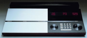
Bang & Olufsen Beomaster 8000
Back in 2008, I was given a Bang & Olufsen Beomaster 8000 that was in non-working condition. The receiver appeared to be the victim of a power surge as well as some failed attempts to fix it. I replaced many blown semiconductors, fixed a burned PC board trace and did lots of general troubleshooting. After several weeks of this, I got it to the point where the unit would power on, but only one channel had a signal at the speaker output and even so, the electronic volume control would not attenuate the signal all the way down to zero. It turned out that two digital volume attenuators were bad - they were Analog Devices AD7110s.
Digi-Key didn’t carry any replacements, nor did other parts suppliers like Mouser. I did some Google searches for anyone else that carried those ICs, but all I came up with were some small vendors that I’ve never heard of before with questionable product descriptions for ICs with a similar product number, but no clear indication that they were volume attenuators. The price seemed way off the mark too, which made me wonder if it was just Black Hat SEO. More recently in 2015 when I created this page, I searched for AD7110s again and had better luck. Now it seems like you can get these devices on eBay from more credible vendors at a reasonable price. I’m not sure if I just missed those the first time around or if things have changed in recent years. Nevertheless, I didn’t have confidence in what I saw online in 2008, so I decided to make a daughter board to simulate the AD7110 with parts that were readily available at the time.
A feature of the AD7110 was that it had the ability to control a 2 stage bass-boost circuit for the lower volume levels. This was supposed to keep the bass from sounding thin when the volume was turned down low. Although there were lots of other volume attenuators for which an adapter could be made to fit the socket on the Beomaster, I couldn’t find anything that had a similar bass boost feature. In the end, I decided to use an AD7111 for the volume attenuation and a PIC 16F688 microcontroller which drove an ADG411 CMOS analog switch to do the bass boost at the appropriate levels. What follows are some photos I took as I was building it, as well as schematics, PC layout and source code. Click on any photo to see it at a higher resolution.
Circuit Details
On the original AD7110, moderate bass boost starts to kick in at 48dB attenuation and somewhat heavier boost starts at 60dB. Finally, everything gets muted when attenuation exceeds 88.5dB. To simulate this, I made a second PC board that piggy-backed on top of the volume attenuator which had a microcontroller to read the volume control input bits and it in turn controlled a CMOS analog switch which would control the Beomaster’s bass boost circuitry.


The AD7110 uses a 6 bit input code whereas the AD7111 uses an 8 bit code. As it turned out, I was able to get the AD7111 to produce the exact same attenuation steps just by hard-wiring the two least significant input bits to ground. Then I used a microcontroller in conjunction with a CMOS analog switch to activate the Beomaster’s bass boost circuitry at low volume levels. After that, all that remained was to make a PC board that would re-route the various power, ground and signal lines to the appropriate pins on the AD7110 socket.
Construction


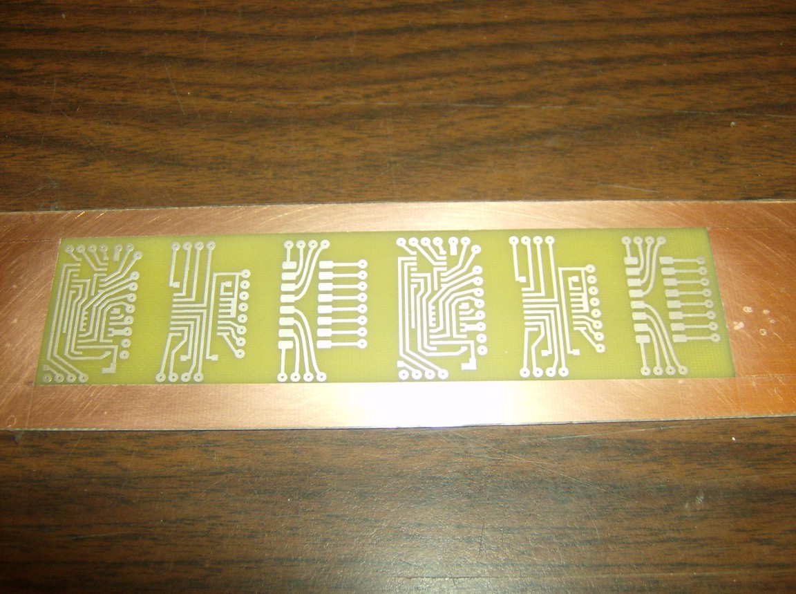
Here are some SVG images of the PC layout. Because these images are vector based, you can click on an image and then use your browser’s zoom feature to see an enlarged view.
I decided to use three separate circuit boards stacked on top of each other because this circuit had to fit a fairly tight space on the Beomaster’s preamp board. Riser leads around the edges of the underside board carry signals, power, etc. to the volume and microcontroller boards that sit on top of it. Also, I was able to use 0.032" PC board material because each board was only about the size of a large postage stamp and therefore rigidity was not a concern. I made the boards using the toner transfer method on Press-n-Peel Blue transfer papers.
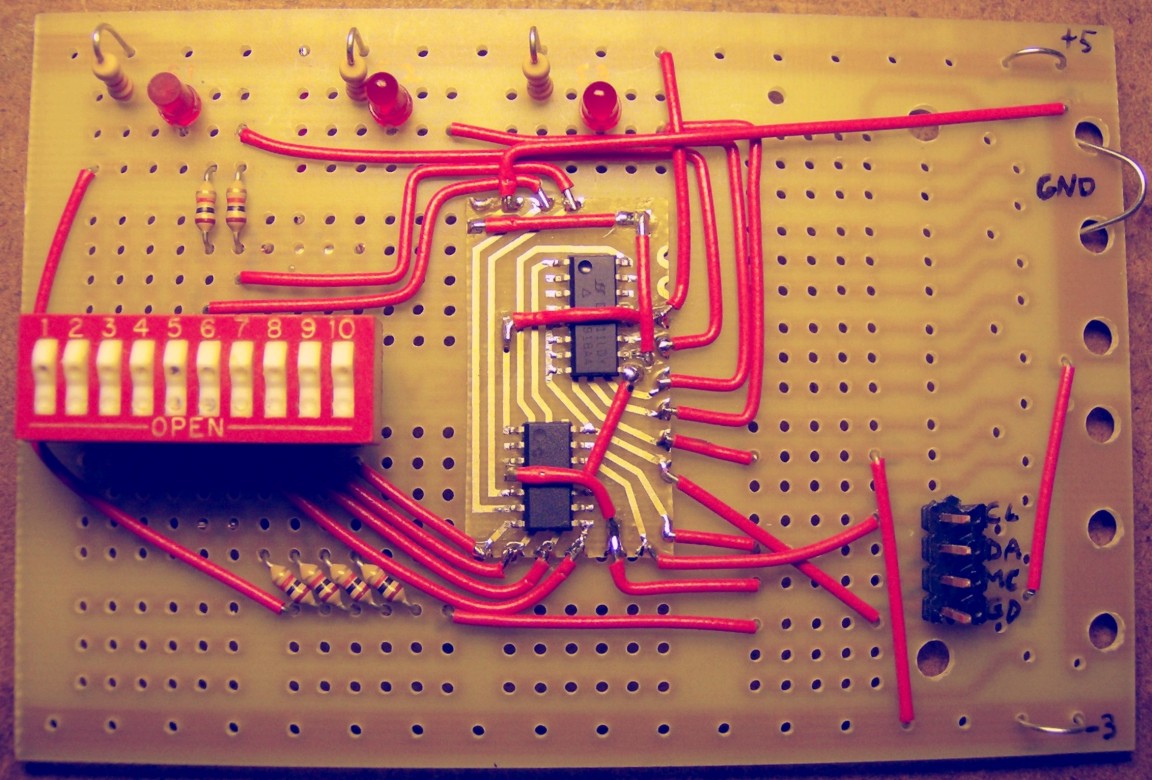
I built the hardware before writing the firmware so there would be a physical prototype that I could use for debugging and testing. To do this, I mounted one of the finished PC boards on a perfboard test rig. DIP switches were used to simulate the 6 bit attenuation value and LEDs were used to indicate when the bass boost and muting stages were active. The circuit was designed so that the microcontroller pins used for in circuit programming were not used for any other task, which allowed the microcontroller to be easily re-programmed if needed. A four pin header which can be seen in the lower right corner of the test rig, was used for programming the microcontroller.
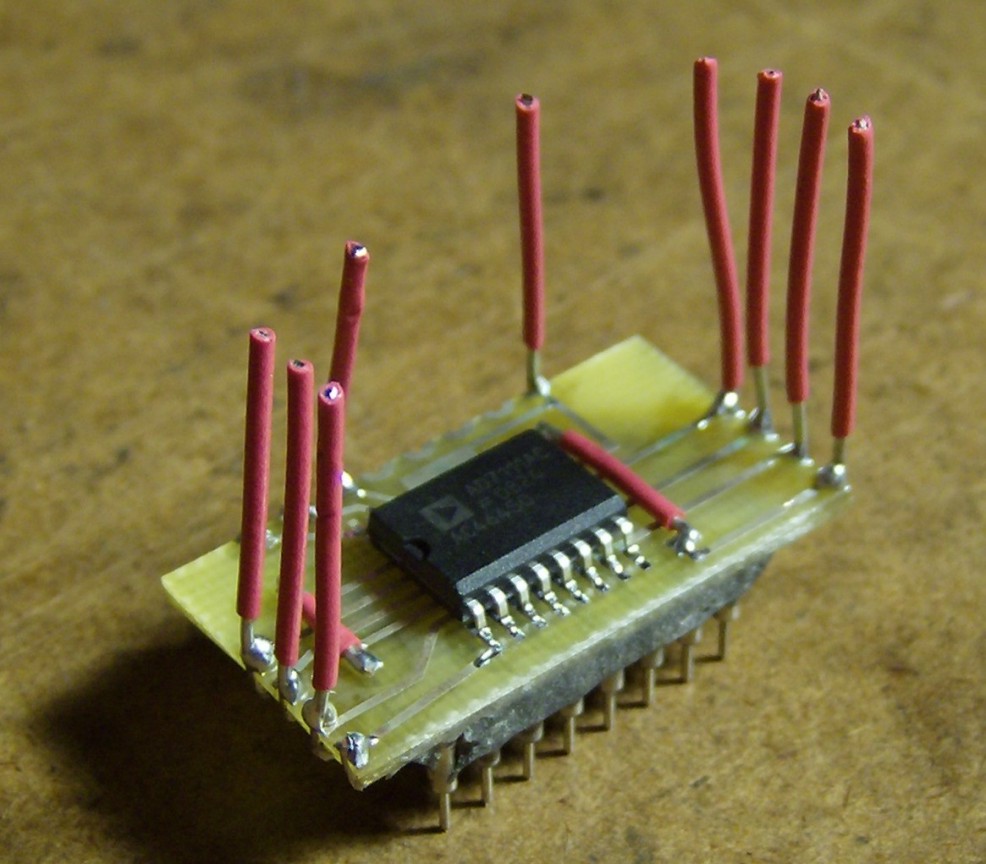
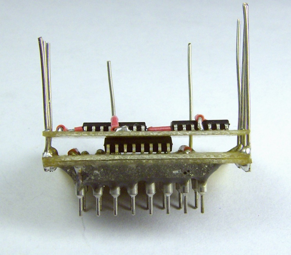
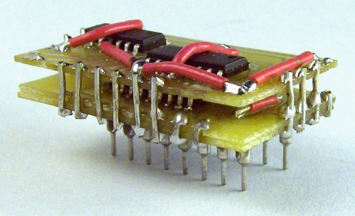
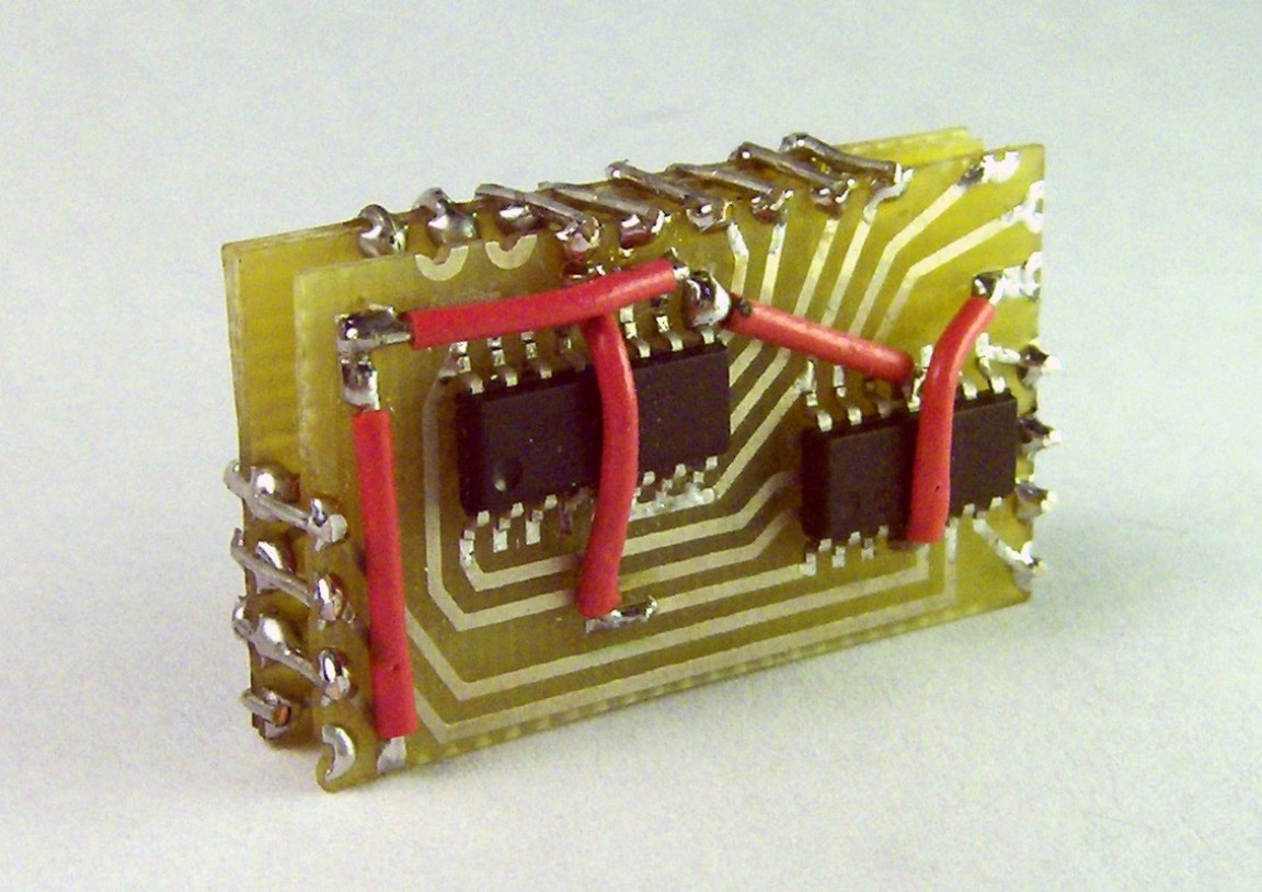
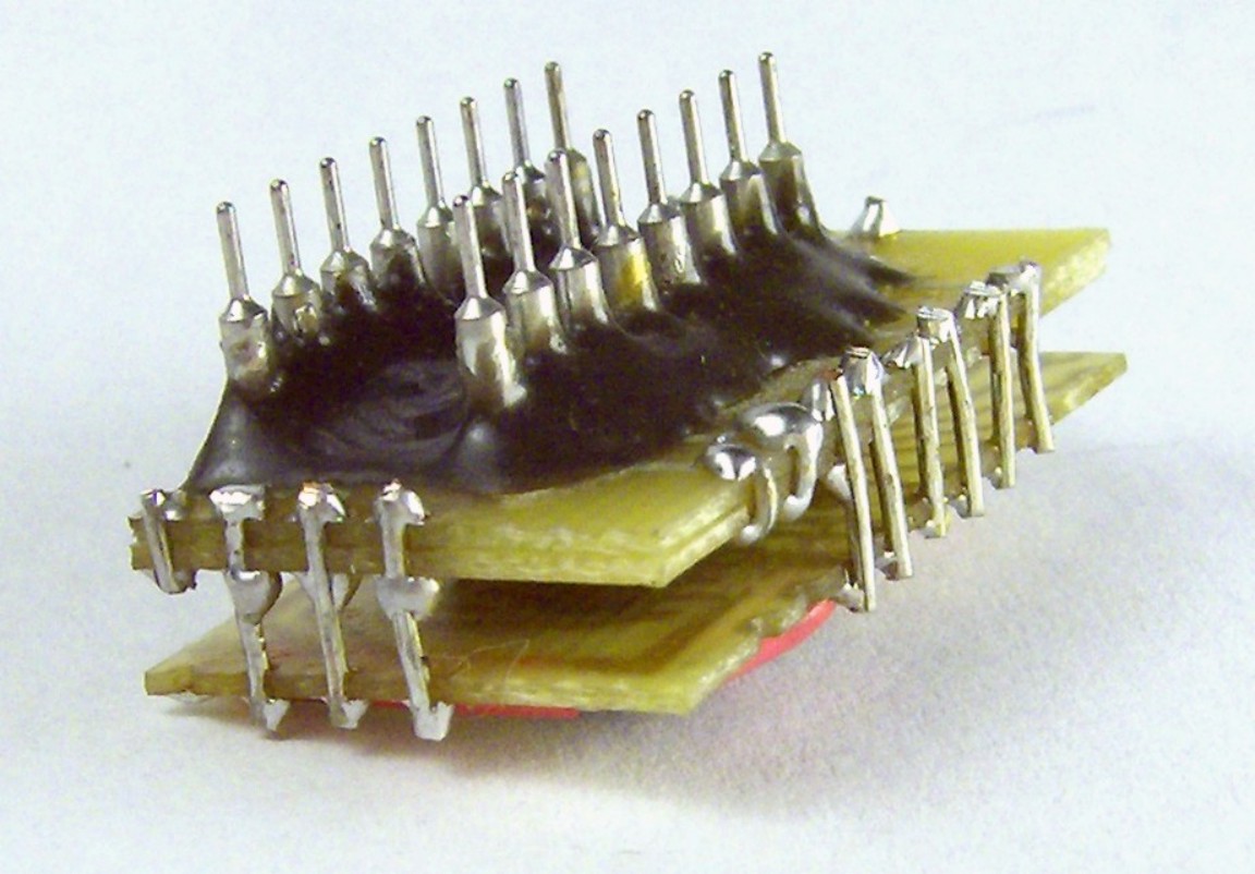
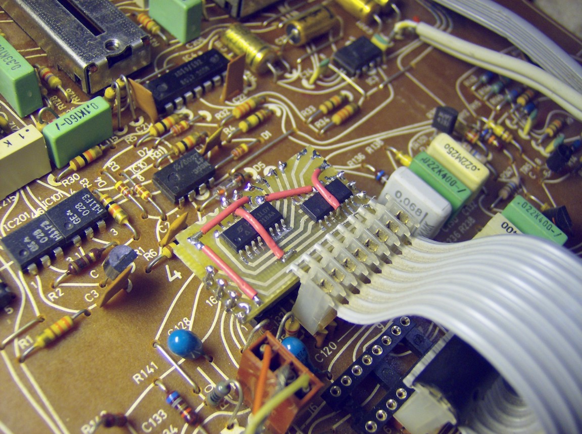
Since the daughter board was designed as a plug-in replacement for the original AD7110 volume attenuator, I soldered machined IC socket pins directly to the underside circuit board that matched the pin spacing of the original IC. Once the pins were soldered in place, they were reinforced with epoxy so they could withstand the strain of being inserted and removed from their sockets on the Beomaster 8000 preamp board. One challenge I faced was to find a way to get the alignment of the pins perfect so they would easily plug into the AD7110’s socket. To solve this, I used my mini mill. Because the mini mill had a table that could move in the X and Y axes by way of a leadscrew and handwheel that was graduated in 0.001 inch increments, I could hold a pin in the mill chuck, lower the mill head so the pin touches the circuit board and solder it in place. After that, I would raise the head, turn the X axis handwheel to advance the table by 0.1 inches to the next pad on the circuit board and repeat the process.
Firmware

The firmware for this project is quite simple. Basically, Port C is used as an input to read the volume control data from the Beomaster’s logic board and three lines from Port A are used as outputs to control the bass boost stages and muting. In order to simplify the PC layout, I ran the volume data lines to whichever Port C inputs were most convenient and as a result, the order of the lines is scrambled a bit. This isn’t really a problem though because it’s a trivial matter to rearrange the order of the bits in firmware. So, the microcontroller runs in an endless loop reading the data at Port C, rearranging the order of the bits, then running four different conditional checks to see if low bass boost, higher bass boost, muting, or none should be activated. Based on the results from the conditional checks, the appropriate bass boost and/or muting lines are activated. The numeric ranges in the conditional checks were chosen to match the bass boost and muting thresholds in the original AD7110 chip.
Click here to view the firmware source code in your browser.